Kia Optima Hybrid: Indicators And Gauges / Instrument Cluster Repair procedures
Kia Optima Hybrid (TF HEV) 2016-2020 Service Manual / Body Electrical System / Indicators And Gauges / Instrument Cluster Repair procedures
| Inspection |
| NO | Ref Symbol | Name | Signal Input Message Name | Signal control Signal Value (X: Don’t care) | Illumination/ Power |
| 1 |
| Turn Left | B-CAN | Turn LH Signal Lamp Switch Status for indicator in CLU | LED/ B+ |
| 2 |
| Turn Right | B-CAN | Turn RH Signal Lamp Switch Status for indicator in CLU | LED/ B+ |
| 3 |
| Front Fog | B-CAN | Front Fog ON | LCD/ B+ |
| 4 | - | Rear Fog | B-CAN | Rear Fog IND | LED/ IGN1 |
| 5 |
| High Beam | B-CAN | Head Lamp High ON | LED/ B+ |
| 6 |
| Seat Belt | B-CAN | Driver Seat Belt IND | LED/ IGN1 |
| 7 |
| Door Open | B-CAN | Driver Door Switch Assist Door Switch RR Door Switch RL Door Switch C_DRIVETYPE (0h:LHD,1h:RHD) | LED/B+ TFT LCD/IG |
| 8 |
| Trunk Open | B-CAN | Tail Gate Switch | LED/B+ TFT LCD/IG |
| 9 |
| Immobilizer | Hardwire (SMK) | Input terminal is GND | LED/ B+ |
| C-CAN (EMS) | EMS Immo Lamp (Non-SMK) | LED/ IG+ | |||
| 10 |
| ABS | C-CAN TCS | ABS Warning Lamp | LED/ IG+ |
| 11 |
| Parking Brake | C-CAN TCS | Brake Warning Lamp | LED/ IG+ |
| B-CAN | Parking Brake Switch Brake Fluid Switch | ||||
| Brake Fluid Sensor (Hard wire) | Input terminal is GND | ||||
| AHB | AHB Warning Lamp | ||||
| 12 |
| ESC | C-CAN TCS | Brake TCS Lamp | LED/ IG |
| 13 |
| ESC OFF | Brake TCS Warning Lamp | LED/ IG | |
| 14 |
| Air Bag | C-CAN ACU | Active circuit | LED/ Air/B+- |
| 15 |
| Oil Pressure | Hardwire | Input terminal is GND ISG control(MICOM) | LED/ IG |
| 16 |
| Alternator | C-CAN LDC | LDC Aux Bat Warning Lamp | LED/ IG |
| 17 |
| Check Engine | C-CAN EMS | EMS Mil Request | LED/ IG |
| 18 |
| Low Fuel | When LOW FUEL resistance is inputted | MCU Control | LED/ IG |
| 19 | CRUISE | CRUISE | C-CAN HCU | HCU Cruise On Lamp | LCD/ IG |
| 20 | SET | SET | HCU Cruise Set Lamp | LCD/ IG | |
| 21 |
| TPMS (TREAD) | C-CAN TPMS | TPMS Tread Warning Lamp | LED, Dispaly/ IG |
| TPMS Fail | TPMS Warning Lamp | LED/ IG | |||
| 22 |
| Tail Lamp | B-CAN | INT Tail Act | LCD/ B+ |
| 23 | EPS | EPS (MDPS) | C-CAN MDPS | MDPS Warning Lamp | LED/ IG |
| 24 |
| HIGH TEMP WARNING | C-CAN EMS | EMS Eng Cool Temp | LED/ IG |
| 25 |
| SERVICE | C-CAN HCU | HCU Service Lamp | LED/ IGN |
| MCU | MCU Service Lamp GCU Service Lamp | ||||
| BMS | BMS Service Lamp | ||||
| LDC | LDC Service lamp Request | ||||
| TCU | TCU Service Lamp | ||||
| OPU | OPU Service Lamp | ||||
| 26 | - | READY | C-CAN HCU | HCU HEV Ready | LCD/ IGN |
| 27 | - | Washer Low | Hardwire | MCU Control SYMBOL (x), Display | Display/IG+ |
| 28 | - | AAF | AAF | AAF Warning Lamp | Display/IG+ |
| 29 | - | AHB | AHB | AHB Warning MSG | Display/IG+ |
| 30 | - | LDC | | LDC Aux Bat Warning Alarm | Display/IG+ |
| 31 |
| EV MODE | HCU | HCU HEV Ready | LED/ IG+ |
Speedometer
| 1. |
Adjust the pressure of the tires to the specified level. |
| 2. |
Drive the vehicle onto a speedometer tester. Use wheel chocks (A) as appropriate. |
| 3. |
Check if the speedometer indicator range is within the standard values.
[Canada - km/h]
[USA - MPH]
|
Fuel Gauge
| 1. |
Disconnect the fuel sender connector from the fuel sender. |
| 2. |
Connect a 3.4 watt, 12V test bulb to terminals 1 and 3 on the wire harness side connector. |
| 3. |
Turn the ignition switch to the ON, and then check that the bulb lights up and the fuel gauge needle moves to full.
|
Main Fuel Gauge Sender
| 1. |
Using an ohmmeter, measure the resistance between terminals 1 and 3 of sender connector (A) at each float level.
|
| 2. |
Also check that the resistance changes smoothly when the float is moved from "E" to "F"
[Supervision]
|
| 3. |
If the height resistance is unsatisfied, replace the fuel sender as an assembly.
|
Engine Coolant Temperature Sender
| 1. |
Information of engine coolant temperature is inputed via CAN communication and displayed on cluster LCD. |
| 2. |
Engine coolant temperature specification
|
Brake Fluid Level Warning Switch
| 1. |
Remove the connector (A) from the switch located at the brake fluid reservoir. |
| 2. |
Verify that continuity exists between switch terminals 1 and 2 while pressing the switch (float) down with a rod.
|
Brake Fluid Level Warning Lamp
| 1. |
Ignition "ON" |
| 2. |
Release the parking brake. |
| 3. |
Remove the connector from the brake fluid level warning switch. |
| 4. |
Ground the connector at the harness side. |
| 5. |
Verify that the warning lamp lights. |
Parking Brake Switch
The parking brake switch (A) is a pulling type. It is located
under the parking brake lever. To adjust, move the switch mount up and
down with the parking brake lever released all the way.
| 1. |
Check that there is continuity between the terminal and switch body with the switch ON (Lever is pulled). |
| 2. |
Check that there is no continuity between the terminal and switch body with the switch OFF (Lever is released).
If continuity is not as specified, replace the switch or inspect its ground connection.
|
Door Switch
Remove the door switch and check for continuity between the terminals.


Seat Belt Switch
| 1. |
Remove the connector from the switch. |
| 2. |
Check for continuity between terminals.
|
Seat Belt Warning Lamp
With the ignition switch turned ON, verify that the lamp glows.
| Seat belt condition | Warning lamp |
| Fastened | OFF |
| Not fastened | ON |
| Removal |
|
| 1. |
Disconnect the negative (-) battery terminal. |
| 2. |
Using a screwdriver or remover, remove the crash pad garnish RH (A).
|
| 3. |
Using a screwdriver or remover, remove the crash pad side cover (A).
|
| 4. |
After loosening the crash pad lower panel mounting screws, then remove the lower panel (A).
|
| 5. |
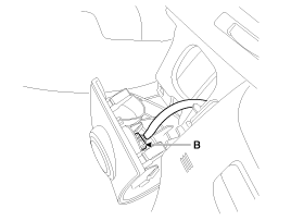
Remove the switch connector (A) and SSB connector (B) from crash pad lower panel.
|
| 6. |
Remove the crash pad garnish LH (A) after removing the screws.
|
| 7. |
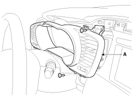
Remove the instrument cluster fascia panel (A) after loosening the screws.
|
| 8. |
Remove the instrument cluster (A) after loosening the screws.
|
| 9. |
Disconnect the cluster connector (A), then remove the cluster.
|
| Installation |
| 1. |
Install the cluster to the cluster housing. |
| 2. |
Install the cluster fascia panel and crash pad side garnish [LH]. |
| 3. |
Install the crash pad lower pannel and side cover. |
| 4. |
Install the side pad garnish [RH]. |
 Instrument Cluster Schematic Diagrams
Circuit Diagram ...
 Trip Switch Schematic Diagrams
Circuit Diagram ...
Other information:
Kia Optima Hybrid (TF HEV) 2016-2020 Service Manual: Speakers Repair procedures
Inspection 1. Troubleshooting for Speaker (1) Basic inspection of speaker Inspect the sound from speaker after verifying that the speaker mounting screws are removed and the wiring connector is connected to remove any possible vibration transmitted from body trims and surrounding parts. (2) Case Troubleshooting ...
Kia Optima Hybrid (TF HEV) 2016-2020 Service Manual: Special Service Tools
Special Service Tools Tool(Number and Name)IllustrationUseDeployment tool0957A-34100AAirbag deployment tool.Deployment adapter0957A-3Q100Use with deployment tool.(DAB, CAB, BPT, APT)Deployment adapter0957A-2E110Use with deployment tool.(PAB)Deployment adapter0957A-3F100Use with deployment tool.(SAB)Dummy0957A-38200Simulator ...
© 2025 Copyright www.koptimatfhev.com


