Kia Optima Hybrid: Engine Mechanical System / High Voltage Shut-off Procedures
Kia Optima Hybrid (TF HEV) 2016-2020 Service Manual / Engine Mechanical System / High Voltage Shut-off Procedures
| High Voltage Shut-off Procedures |
Be sure to read and follow the “General Safety Information
and Caution” before doing any work related with the high voltage
system. Failure to follow the safety instructions may result in serious
electrical injuries. |
|
| 1. |
Turn the ignition switch OFF and disconnect the auxiliary 12V battery negative (-) terminal. |
| 2. |
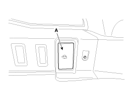
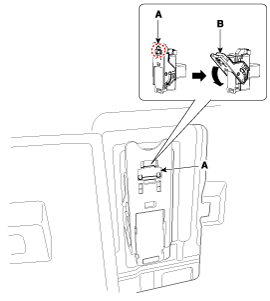
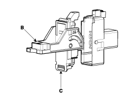
Remove the safety plug.
|
| 3. |
Wait for more than 5 minutes so that the capacitor in the high voltage system can be fully discharged. |
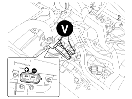
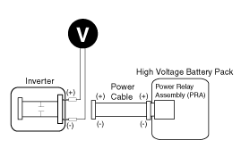
| 4. |
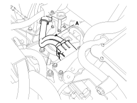
Measure the voltage between the inverter terminals to check that the capacitor in the inverter is discharged completely
|
 General Safety Information and Caution
Safety Precaution Since hybrid vehicles contain a high voltage battery, if the high voltage system or vehicles are handled incorrectly, this might lead to a serious accidents like electric ...
 Specifications
Specifications DescriptionSpecificationsLimitGeneralTypeIn-line, DOHC?Number of cylinders4?Bore88mm (3.464in.)?Stroke97mm (3.819in.)?Total displacement2359cc (143.90cu.in)?Compression ratio13.0 ± 0.3 ...
Other information:
Kia Optima Hybrid (TF HEV) 2016-2020 Service Manual: Components and Components Location
Component Location 1. Auto light sensor2. Head lamps3. Lighting switch (Auto)4. Tail lamps5. Body control module (BCM) ...
Kia Optima Hybrid (TF HEV) 2016-2020 Service Manual: Fluid Components and Components Location
Component Location 1. ATF fill hole (eyebolt) 2. ATF level plug3. ATF drain plug ...
© 2025 Copyright www.koptimatfhev.com


